Two-Piece Propeller Shaft Replacement
Two-Piece Propeller Shaft Replacement
Tools Required
J 43218 Clamp Pliers - Narrow Jaw
Removal Procedure
Important: Observe and accurately reference mark all driveline components relative to the propeller shaft and axles before disassembly. These components include the propeller shafts, the drive axles, the pinion flanges, the output shafts, etc. All components must be reassembled in the exact relationship to each other as they were when removed. In addition, published specifications and torque values, as well as any measurements made prior to disassembly must be followed.
1. Raise the vehicle. Refer to Lifting and Jacking the Vehicle .
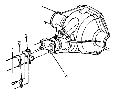
2. Reference mark the rear propeller shaft (3) to the rear axle pinion yoke (4).
3. Reference mark the front propeller shaft to the transmission or transfer case (slip yoke type) or to the transmission pinion yoke (universal joint type).
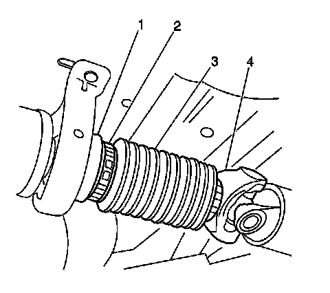
4. Remove the clamp (2) securing the boot (3) to the front propeller shaft stub shaft (4) and the rear propeller shaft slip yoke (1) by prying up the exposed end of the clamp (2) using a flat-bladed tool, if applicable.
5. Remove the bolts (1) and the yoke retainers (2) from the rear axle pinion yoke (4).
Notice: When removing the propeller shaft, do not attempt to remove the shaft by pounding on the yoke ears or using a tool between the yoke and the universal joint. If the propeller shaft is removed by using such means, the injection joints may fracture and lead to premature failure of the joint.
6. Slide the rear propeller shaft forward in order to remove the propeller shaft from the rear axle pinion yoke.
7. Slide the rear propeller shaft rearward in order to disconnect the rear propeller shaft from the front propeller shaft stub shaft.
8. Remove the rear propeller shaft from the vehicle.
9. Remove the boot from the front propeller shaft stub shaft, if applicable.
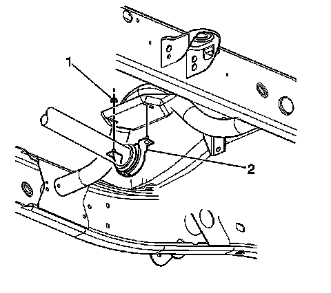
10. Remove the center bearing support nuts (1).
11. Remove the center bearing support (2).
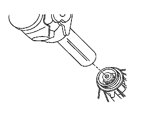
12. Remove the front propeller shaft by sliding the front propeller shaft rearward from the transmission or the transfer case, w/o RPO MW3 or M74.
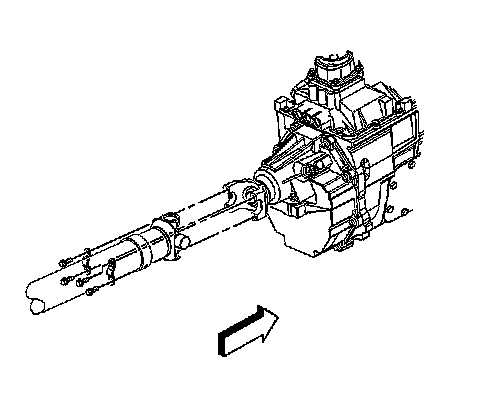
13. Remove the bolts and the yoke retainers from the transmission pinion yoke, w/ RPO MW3 or M74.
14. Remove the front propeller shaft by disconnecting the front propeller shaft from the transmission pinion yoke, w/ RPO MW3 or M74.
Installation Procedure
1. Install the front propeller shaft by sliding the front propeller shaft into the transmission or the transfer case, w/o RPO MW3 or M74.
2. Install the front propeller shaft to the transmission pinion yoke, w/ RPO MW3 or M74.
Important:
* Align the reference marks made during removal.
* Tighten the bolts until snug. Do not torque the bolts at this time.
3. Install the yoke retainers and the bolts, w/ RPO MW3 or M74.
4. Install the center bearing support (2).
Notice: Refer to Fastener Notice .
5. Install the center bearing support nuts.
Tighten the bearing support nuts to 40 N.m (30 lb ft).
6. Tighten the yoke retainer bolts, w/ RPO MW3 or M74.
Tighten the yoke retainer bolts to 25 N.m (18 lb ft).
7. Inspect the splines of the front propeller shaft stub shaft for a sufficient coating of grease. If the splines of the stub shaft does not have a sufficient coating of grease, lubricate the shaft with chassis grease, GM P/N 12377985 or equivalent.
8. Install the boot (3) and 2 new clamps (2) onto the front propeller shaft stub shaft (4), if applicable.
9. Install the rear propeller shaft slip yoke onto the front propeller shaft stub shaft.
Mate the missing tooth in the yoke with the bridged tooth on the splined shaft.
10. Install the rear propeller shaft onto the rear axle pinion yoke.
Align the reference marks made during removal.
11. Install the yoke retainers (2) and the bolts (1).
Tighten the yoke retainer bolts to 25 N.m (18 lb ft).
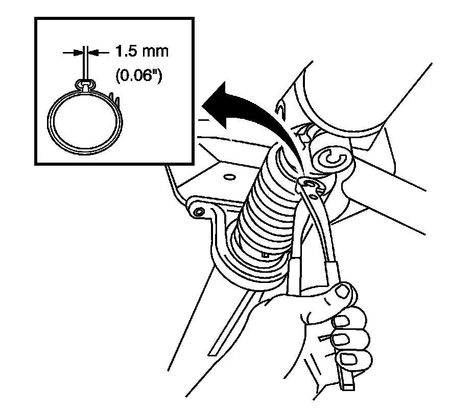
12. Using the J 43218 , crimp the boot clamps until the dimensions shown are obtained.
13. Lower the vehicle.