Rear Axle Shaft Replacement (8.6 Inch Axle w/Drum Brakes W/O VSES)
Rear Axle Shaft Replacement (8.6 Inch Axle w/Drum Brakes w/o VSES)
Removal Procedure
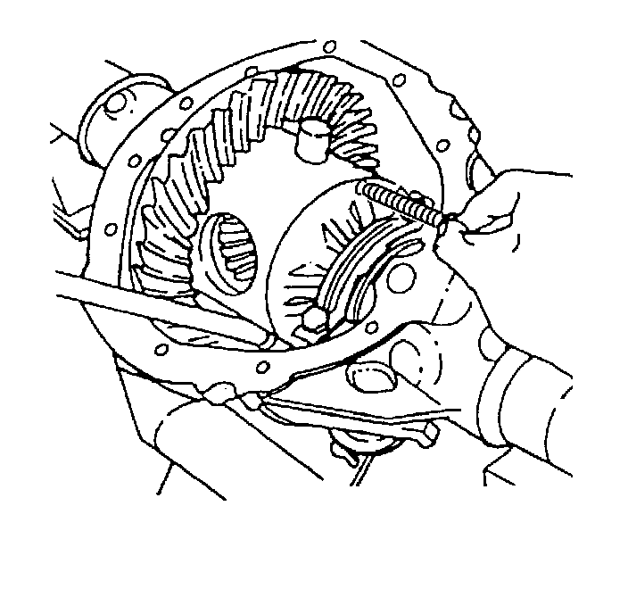
1. Raise and support the vehicle. Refer to Lifting and Jacking the Vehicle .
2. Remove the tire and wheel assembly. Refer to Tire and Wheel Removal and Installation (Service and Repair) .
3. Remove the rear cover and gasket. Refer to Rear Axle Housing Cover and Gasket Replacement (Service and Repair) .
4. Remove the pinion shaft locking bolt.
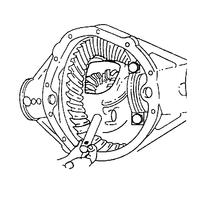
5. On axles without a locking differential, remove the pinion shaft.
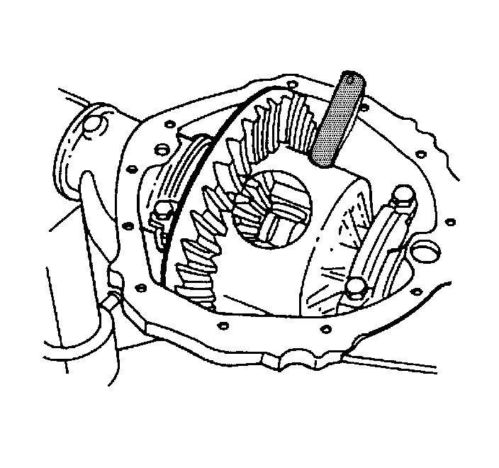
6. On axles with a locking differential, remove the shaft part way. Rotate the case until the pinion shaft touches the housing.
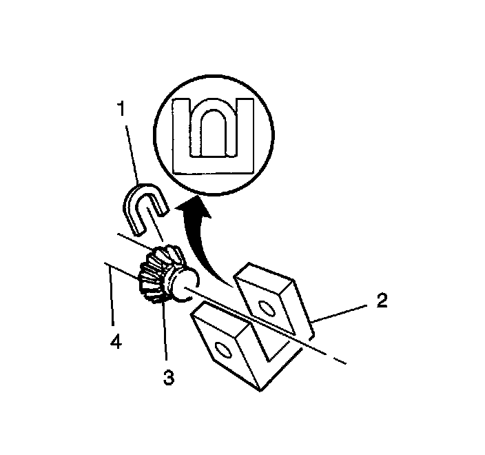
7. On axles with a locking differential, use a screwdriver, or a similar tool, in order to enter the differential case and rotate the lock (1) until the lock aligns with the thrust block (2).
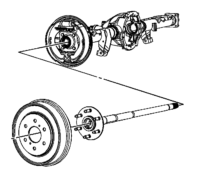
8. Remove the brake drum.
9. Push the flange of the axle shaft in toward the differential.
10. Remove the C-lock from the button end of the axle shaft.
Important: When removing the axle shaft, do not rotate the shaft. Rotating the shaft will misalign the gears. Misaligning the gears will make assembly difficult.
11. Remove the axle shaft from the housing.
Installation Procedure
Important: Carefully insert the axle shaft in order to not damage the seal.
1. Install the axle shaft into the rear axle housing.
2. Slide the axle shaft into place allowing the splines to engage the differential side gear.
3. On axles without a locking differential, place the C-lock on the button end of the axle shaft.
4. On axles with a locking differential, keep the pinion shaft partially withdrawn.
5. Install the brake drum.
6. On axles with a locking differential, place the C-lock (1) on the axle shaft (3) so that the ends are flush with the thrust block (2).
7. Pull the shaft flange outward in order to seat the lock in the differential gear.
8. Align the hole in the pinion shaft with the bolt hole in the differential case.
Notice: Refer to Fastener Notice .
9. Install the new pinion shaft locking bolt.
Tighten the bolt to 34 N.m (25 lb ft).
10. Install the rear cover and the gasket. Refer to Rear Axle Housing Cover and Gasket Replacement (Service and Repair) .
11. Install the tire and wheel assembly. Refer to Tire and Wheel Removal and Installation (Service and Repair) .
12. Fill the rear axle, using the proper fluid. Refer to Approximate Fluid Capacities and Fluid and Lubricant Recommendations .
13. Lower the vehicle.