Idler Arm: Service and Repair
Idler Arm Replacement
Tools Required
J 24319-B Steering Linkage and Tie Rod Puller
Removal Procedure
Notice: Do not attempt to free the ball stud by using a pickle fork or wedge type tool, because seal or bushing damage could result. Use the proper tool to separate all ball joints.
1. Remove the engine shield, if equipped. Refer to Engine Shield Replacement .
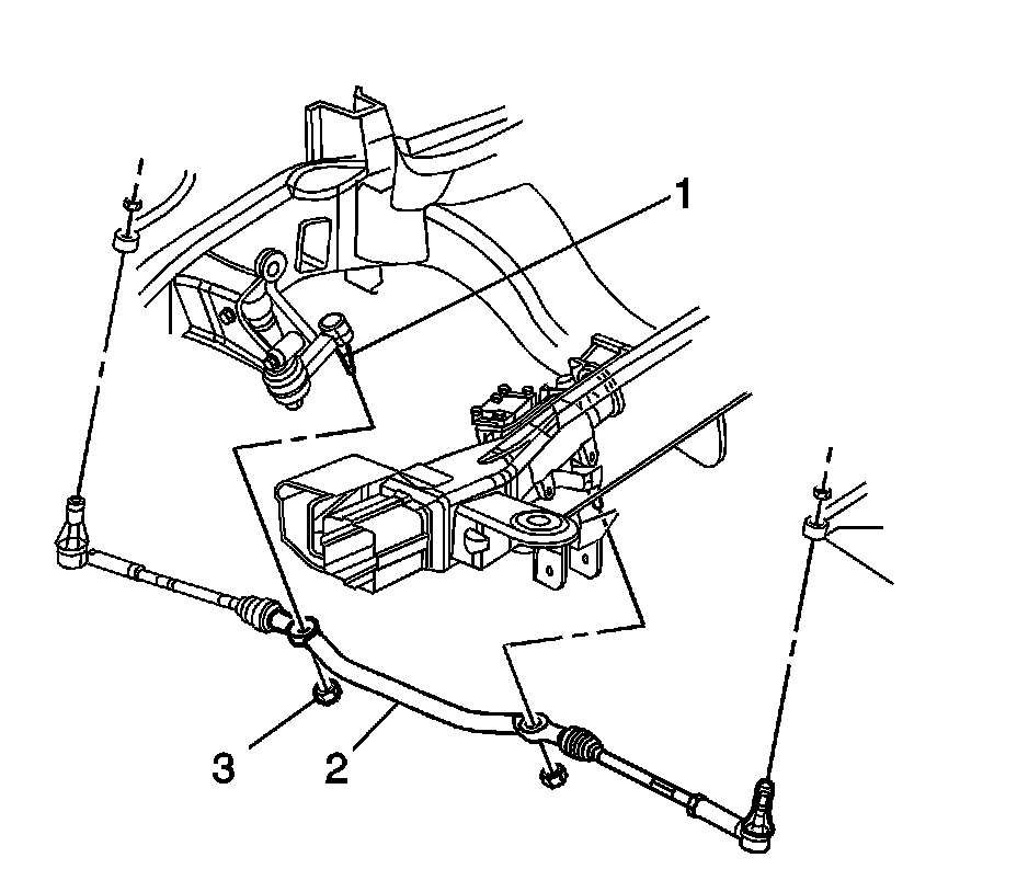
Important: Discard the idler arm nut.
2. Remove the idler arm nut (3) from the idler arm (1).
3. Separate the idler arm (1) from the relay rod (2).
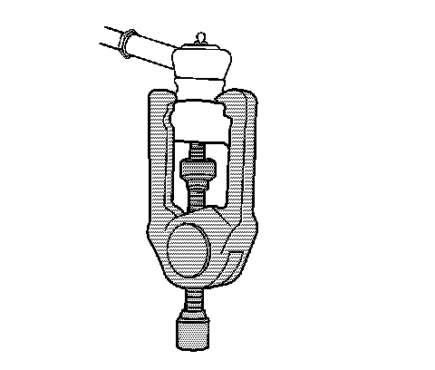
4. Remove the idler arm from the relay rod using puller J 24319-B .
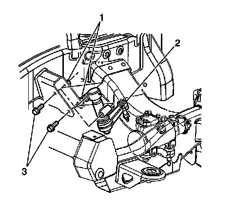
5. Remove the idler arm bolts (3) and the nuts (1) at the vehicle frame.
6. Remove the idler arm (2) from the vehicle.
Installation Procedure
1. Position the idler arm (2) to the vehicle frame.
Notice: Refer to Fastener Notice .
2. Install the idler arm bolts (3) and nuts (1) to the frame.
Tighten the bolts and nuts to 105 N.m (78 lb ft).
3. Install the idler arm (1) to the relay rod (2).
Important: Do not reuse the old idler arm nut.
4. Install the new idler arm nut (3) to the idler arm (1).
Tighten the nut to 62 N.m (46 lb ft).
5. Install the engine shield, if equipped. Refer to Engine Shield Replacement .
6. Adjust the front toe. Refer to Front Toe Adjustment (Service and Repair) .